Lead tin phase diagram lab report. Lab 4 (PbSn Phase Diagram) 2022-10-12

Lead tin phase diagram lab report Rating: 4,5/10 1618 reviews

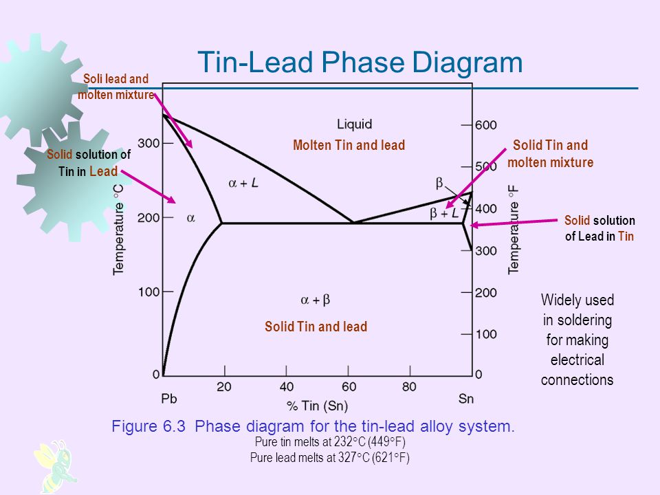
A lead-tin phase diagram is a graphical representation of the different phases or states of a binary alloy system, in this case a mixture of lead and tin, as a function of temperature and composition. It is a useful tool for understanding the behavior of the alloy at different temperatures and compositions, and can be used to predict the microstructure and properties of the alloy.

In a lead-tin phase diagram lab report, the purpose of the experiment is usually to determine the phase diagram for the lead-tin alloy system by performing a series of heating and cooling cycles on samples of the alloy with different compositions. This is typically done using a differential scanning calorimeter (DSC), which measures the heat flow between a sample and a reference material as the temperature is changed.

To begin the experiment, the researcher will first prepare a series of alloy samples with different compositions of lead and tin. These samples can be prepared by melting the two metals together in a crucible and casting the alloy into ingots or discs. The composition of each sample is carefully measured and recorded.

Next, the samples are placed in the DSC and the temperature is gradually increased. As the temperature rises, the alloy will go through various phase transitions, such as the solid-solid transformation from the beta phase to the alpha phase, or the solid-liquid transformation as the alloy melts. The DSC measures the heat flow between the sample and the reference material as these phase transitions occur, and this data is used to construct the phase diagram.

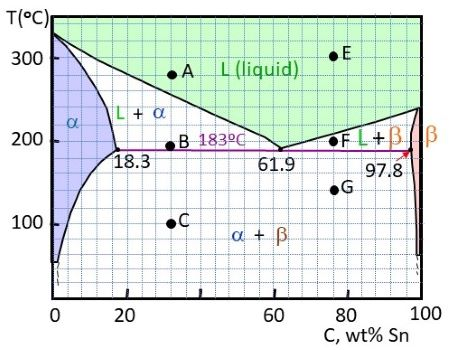
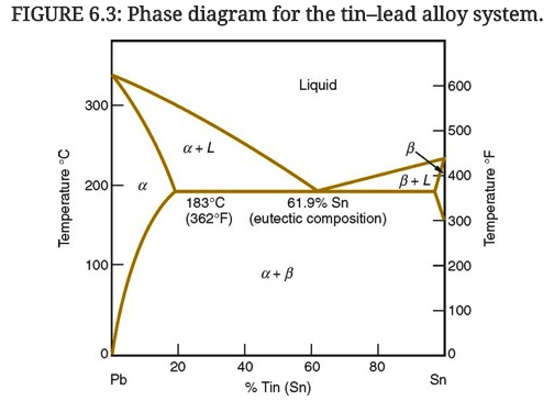
The lead-tin phase diagram is divided into three main regions: the alpha region, the beta region, and the liquid region. The alpha region is the solid state of the alloy at low temperatures, and is characterized by a body-centered cubic (BCC) crystal structure. The beta region is the solid state at higher temperatures, and is characterized by a face-centered cubic (FCC) crystal structure. The liquid region is the molten state of the alloy, in which the atoms are disordered and able to move freely.

The phase diagram also includes several lines or boundaries that mark the transitions between the different phases. The solidus line marks the temperature at which the alloy begins to melt, while the liquidus line marks the temperature at which the alloy is completely melted. The eutectic line marks the composition at which the alloy has the lowest melting point, and the eutectic point marks the temperature at which the eutectic composition is reached.

In a lead-tin phase diagram lab report, the results of the experiment would typically be presented in the form of a graph showing the phase diagram for the lead-tin alloy system. The graph would include the solidus, liquidus, and eutectic lines, as well as the composition and temperature ranges for the alpha, beta, and liquid regions. The report would also include a discussion of the results, including any observations or discrepancies from the expected phase diagram, and any implications for the properties and microstructure of the alloy.

Overall, the lead-tin phase diagram is a valuable tool for understanding the behavior of this alloy system and predicting its microstructure and properties at different temperatures and compositions. By performing a series of heating and cooling cycles using a DSC, researchers can construct the phase diagram and gain valuable insights into the behavior of the alloy.

LEAD

lead tin phase diagram lab report

Thus we can predict that both hypoeutectic and hypereutectic alloys will have a change in slope at the liquidus, and the new slope will be followed by an invariant temperature region and then followed by another change in slope. From the data that was collected, we determined the temperatures that had sudden changes in cooling. Pure Tin The table below lists the different weights of lead and tin used to make the compositions listed above: Table 1: Weights of lead and tin used in the experiment. The linear parts of the cooling curve although does not always have to be linear identify the temperature in °C for the two-phase regions; i. Lead-Tin diagrams were used to predict the percentage of Tin of an unknown alloy.


Next

Lab2

lead tin phase diagram lab report

Phase diagram for the copper-nickel alloy. Phase diagram lab set-up Hot plate Digital Display Thermocouple. Figure 2: Cooling curves for pure lead and pure tin. Introduction A phase diagram is a graphical representation of chemical equilibrium. The starting temperatures used were specified in the lab manual, except the starting temperature of Composition X was set to 290°C, instead of the 320°C specified. This continues until the eutectic temperature, which is about 350˚F for both alloys. Replace jacket into cradle so that the specimen rod is touching the holding screw at one end and the extensometer bar at the other.

Next

Lead

lead tin phase diagram lab report

For example, noting the solidification points and comparison of curves and data were all done manual and are therefore not 100% accurate. Using the specific heat value of the unknown metal and its density, it was determined that the unknown metal was Tin. The purpose of the lab was to observe the rate of cooling alloys of different composition, understand and construct a phase diagram. The image to the right has a few brighter regions than the image to the left. A cooling curve is simply a graph that displays the change of state of a substance over a period of time. Right after the beta + liquid slope is the nearly horizontal line corresponding to the eutectic reaction.

Next

Lab 4 (PbSn Phase Diagram)

lead tin phase diagram lab report

During the process of cooling an alloy can undergo super-cooling undercooling. The difference appears to be in intensity threshold levels. However, this change in slope is probably an inflexion in the data. This continues till all the liquid has been transformed into a mixture of alpha and beta. Ravi Ravindran Teaching Assistant Adam Belcastro Lab Report No.


Next

Tin

lead tin phase diagram lab report

The melting temperatures of pure lead and pure tin are determined from investigating the invariant temperature region in the figure above. Table 4: Experimental temperatures versus book temperatures for 80% tin alloy. In the case of the 40% tin alloy, the image was cut and reduced to the small region where the spots were the brightest. Each alloy is distinct from its components and this enables engineers to decide which alloy is best for determined tasks. Pure lead and tin will also have an invariant temperature region. The conclusion that was made was that through out the entire experiment there was a tremendous amount of error made due to the fact that the percent error was incredibly high.


Next

Lab 2

lead tin phase diagram lab report

The result of this is shown in the figure to the right. The composition of the eutectic phase pf Sn-Pb alloy can be turned into liquid directly from the solid phase, without going through the solid+liquid phase. The percentages obtained were 41. The next smaller slope is due to the beta + liquid phase. Pure Lead 10% Tin 20% Tin 40% Tin Eutectic 61. The final slope is that of the alpha + beta mixture.

Next

determination of phase diagram of lead

lead tin phase diagram lab report

This will be done through observing the time taken for different alloys of tin and lead to cool down to 150°C and form solids. In this experiment we know the water is gaining energy so we know the heat is going to be positive and we can use the equation MCΔT to find the energy change. Phase transformation shows up in the cooling curves in a form similar to that of heating curves. Some of the liquid then precipitates into alpha and the alloys enter an alpha + liquid mixture. THE REPORT: Your Company is interested in the Pb-Sn alloy system as a possible solder material.

Next

Tin lead alloy phase diagram

lead tin phase diagram lab report

The cooling curve for the 10% alloy is shown below: Figure 3: Cooling Curve for 10% Tin alloy. You can find informative and useful articles in this category of Mechanicalland. Users of Mechanicalland become a professional in Solidworks with this category. The five crucibles, all in molten state, were left to cool and the temperatures were recorded in 30 second intervals until the solidification temperature reached 150 degrees celsius. These few changes gave a higher degree of accuracy and justifiable data set for the cooling curves and phase diagram graph.

Next