Friction loss in pipe experiment discussion. Friction loss formula for pipes 2022-10-16
Friction loss in pipe experiment discussion Rating:
8,8/10
345
reviews
Friction loss in pipes is a phenomenon that occurs when a fluid (such as water or air) flows through a pipe and encounters resistance, causing a decrease in pressure and velocity. This phenomenon can have significant impacts on the design and operation of piping systems in a variety of industries, including water treatment, agriculture, and manufacturing.
One way to study and understand friction loss in pipes is through experimentation. In a friction loss experiment, a fluid is flowed through a pipe under controlled conditions, and the pressure and velocity of the fluid are measured at various points along the pipe. By analyzing these measurements, researchers can determine the amount of friction loss that occurs in the pipe and understand how it is affected by factors such as the size and shape of the pipe, the type of fluid being flowed, and the flow rate of the fluid.
There are several factors that can affect the results of a friction loss experiment. For example, the roughness of the interior surface of the pipe can increase friction loss, as the fluid must work harder to flow around rough or irregular surfaces. The size of the pipe is also important, as smaller pipes tend to have higher levels of friction loss due to the increased surface area of the pipe walls relative to the volume of the fluid being flowed. The type of fluid being flowed can also affect friction loss, as some fluids are more viscous and create more resistance as they flow through the pipe.
One way to account for these factors is to use a formula known as the Darcy-Weisbach equation, which is commonly used to calculate the friction loss in pipes. This equation takes into account the size of the pipe, the roughness of the pipe walls, the flow rate of the fluid, and the fluid's viscosity to determine the amount of friction loss that occurs.
In conclusion, friction loss in pipes is an important phenomenon that can have significant impacts on the design and operation of piping systems. Experiments can be conducted to understand and measure friction loss, and the results of these experiments can be used to optimize the design and operation of piping systems to minimize friction loss and improve efficiency.
frictional loss in pipe
The pressure difference for the valve is directly measured by the differential pressure gauge. The procedure was repeated for the for the different pipes which include, rough, smooth, sudden contraction and sudden enlargement pipes. Flow Regime Reynolds Number Friction Factor, f 1 Laminar Equation 4 100 2 200 3 400 4 800 5 1600 6 2000 7 Turbulent Equation 5 4000 8 6000 9 8000 10 10000 11 12000 12 16000 13 20000 10. The head loss was also found to increase with increase in the velocity. This valve should face the volumetric tank, and a short length of flexible tube should be attached to it, to prevent splashing. In this equation, the friction factor f , a dimensionless quantity, is used to describe the friction loss in a pipe.
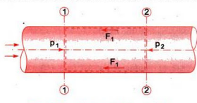
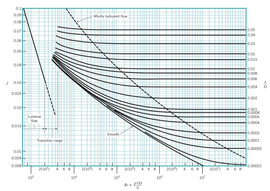
All fluids express some amount of viscosity. On the second graph, plot the K values for the valve y-axis against the flow rate Q x-axis. This can be achieved by several trials of timed volumetric flow measurements. For high flow rate experiments, the inlet pipe is connected directly to the bench water supply. The head loss due to friction can be calculated from the Darcy-Weisbach equation: where: : head loss due to flow resistance f: Darcy-Weisbach coefficient L: pipe length D: pipe diameter v: average velocity g: gravitational acceleration. By assuming the pipes are smooth the Reynolds numbers at their respective flow rates can be used to read off a moody chart by using the smooth pipe lines. This change of energy is usually referred to as friction head loss, which represents the amount of energy converted into heat per unit weight of fluid.
Experiment 1_Friction loss along a pipe lab report. webapi.bu.edu
Major losses are associated with frictional energy loss that is caused by the viscous effects of the medium and roughness of the pipe wall. Pipe Friction Loss Calculations Flow of fluid through a pipe is resisted by viscous shear stresses within the fluid and the turbulence that occurs along the internal pipe wall, which is dependent on the roughness of the pipe material. The slope of this linear relationship showed that as the flow rate increases, the velocity increases which means the Reynolds Number gets bigger and the head loss coefficient increases. Instead of using the Moody diagram, f can be determined by utilizing empirical formulas. But the friction loss is connected to the flow of liquid through a pipe. The total head loss, h L, includes both major and minor losses.
Then tighten the air bleed screw. Part A: In this part, head losses caused by fittings, except for the gate valve, will be measured; therefore, this valve should be kept fully open throughout Part A. Fig 6 — Reynolds number against friction factor of pipe 1 Fig 7 — Reynolds number against friction factor of pipe 2 Fig 8 — Reynolds number against friction factor of pipe 3 From these graphs it can clearly be seen that at the same Reynolds numbers, pipe 2 has a much greater friction factor than the other pipes which provides further evidence that pipe 2 has a much greater roughness which is why all the experimental data has deviated so much in pipe 2 since it was assumed to be smooth. As the flow rate, Q was changed, the values for the inlet and outlet, H1 and H2 were measured. Major losses create a pressure drop along the pipe since the pressure must work to overcome the frictional resistance. What is the dependence of head losses across pipe fittings upon the velocity head? Common Friction Factor Values of C hw used for design purposes are: Asbestos Cement 140 Brass tube 130 Cast-Iron tube 100 Concrete tube 110 Copper tube 130 Corrugated steel tube 60 Galvanized tubing 120 Glass tube 130 Lead piping 130 Plastic pipe 140 PVC pipe 150 General smooth pipes 140 Steel pipe 120 Steel riveted pipes 100 Tar coated cast iron tube 100 Tin tubing130 Wood Stave 110 These C hw values provide some allowance for changes to the roughness of internal pipe surface, due to pitting of the pipe wall during long periods of use and the build up of other deposits. Calculations Calculate the values of the discharge; average flow velocity; and experimental friction factor, f using Equation 3, and the Reynolds number for each experiment.
Open the bench valve progressively, and run the flow until all air is purged. Whenever a fluid flow through a pipe, there will be some friction losses. Experimental Procedure The experiment will be performed in two parts: high flow rates and low flow rates. Introduction The total energy loss in a pipe system is the sum of the major and minor losses. Gates, "Fluid Flow-A First Course of Fluid Mechanics" Fourth Edition , Prentice Hall Inc. Collect water for at least one minute to minimize errors in the flow measurement. Therefore we measured the friction factor of the pipes using our measurements.
Turbulent flow has characteristics of irregular movement of particles with lateral mixing occurring and the flow also is also characterised by eddies and recirculation. Also, calculate the theoretical friction factor, f, using Equation 4 for laminar flow and Equation 5 for turbulent flow for a range of Reynolds numbers. As shown in Figure 5 below the theoretical efflux time for pipe 2 was slightly less than the observed time at each interval. Due to the complexity of the piping system and the number of fittings that are used, the head loss coefficient K is empirically derived as a quick means of calculating the minor head losses. Also the Hazen-Williams equation only really gives good results when the fluid is Water and can produce large inaccuracies when this is not the case.
Pipe 1 and 3 have similar friction factors at the same Reynolds numbers and with relatively low friction factors which provides evidence that they were relatively smooth and so conformed to the assumptions of the experiment more accordingly. Problem 1: Compute the friction loss, if the inner diameter and length of the pipe are 0. Indicate any reason for lack of agreement. The relative roughness value obtained for the pipe was 0. Pressure drop was also seen to be directly proportional to the flow rate in laminar and directly proportional to the squared flow rate in the turbulent regime. As the valve is slowly turned closed, the Major Head Loss due to friction along the pipe, decreases, and the Minor Head Loss, due to the friction through the gate valve, increases.
The shear stress of a flow is also dependent on whether the flow is turbulent or laminar. What is the cumulative effect of the experimental errors on the values of K and n? This does not occur in laminar flow however due to the velocities being too small for there to be a noticeable square relationship but as flow rate and velocity increases the relationship becomes more prominent which is why it can be seen in turbulent regimes. Department of Energy, Thermodynamics, Heat Transfer, and Fluid Flow. If the diameter through the pipe fitting is kept constant, then. Other factors, such as roughness spacing and shape, may also affect the value of f; however, these effects are not well understood and may be negligible in many cases.