Propeller clock project. LED Propeller Clock : 19 Steps (with Pictures) 2022-10-11

Propeller clock project Rating: 9,2/10 738 reviews

A propeller clock is a unique and visually striking timekeeping device that uses a spinning propeller to display the time. This project involves designing and building a clock that utilizes a small motor and a series of gears to rotate a propeller at a consistent speed. The propeller is marked with numerals or other indicators that allow the observer to read the time as the propeller spins.

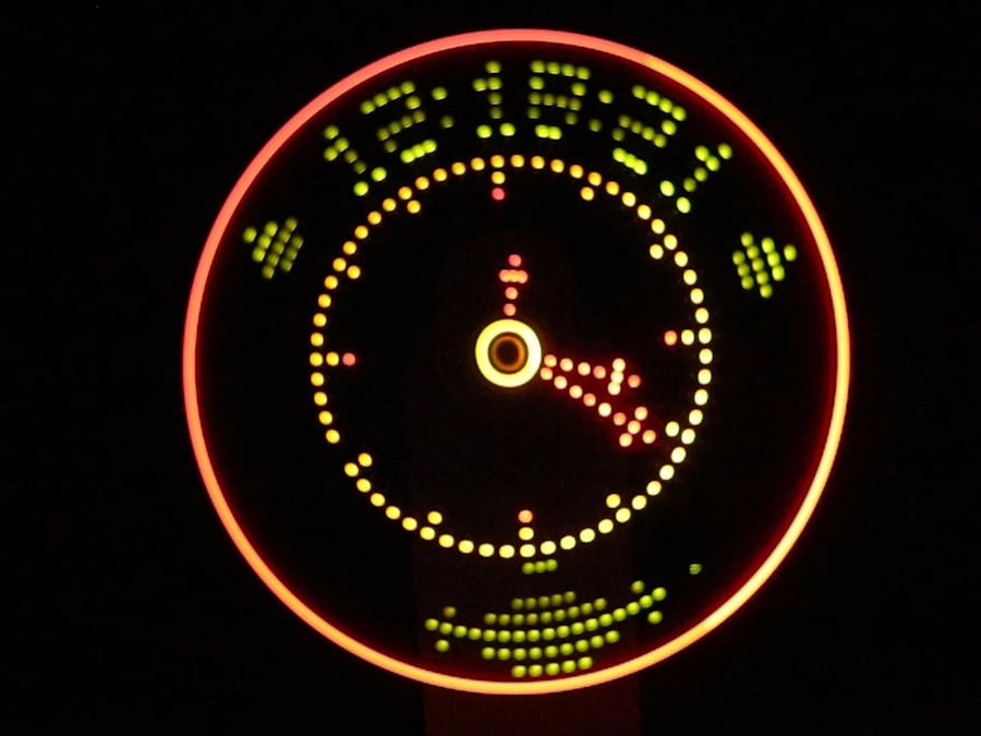
The first step in creating a propeller clock is to design the propeller itself. The propeller should be large enough to be easily readable from a distance, and it should be marked with clear and distinct indicators for the hours, minutes, and seconds. The markings should be evenly spaced around the circumference of the propeller, and they should be positioned so that they are easily visible as the propeller spins.

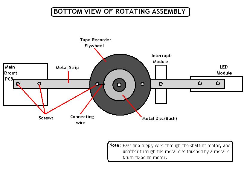
Next, the motor and gears must be selected and assembled. The motor should be powerful enough to rotate the propeller at a consistent speed, but it should not be so powerful as to cause the clock to vibrate or make excessive noise. The gears should be chosen based on the size of the propeller and the desired speed of rotation. The gears should be carefully aligned and secured to ensure that they function smoothly and accurately.

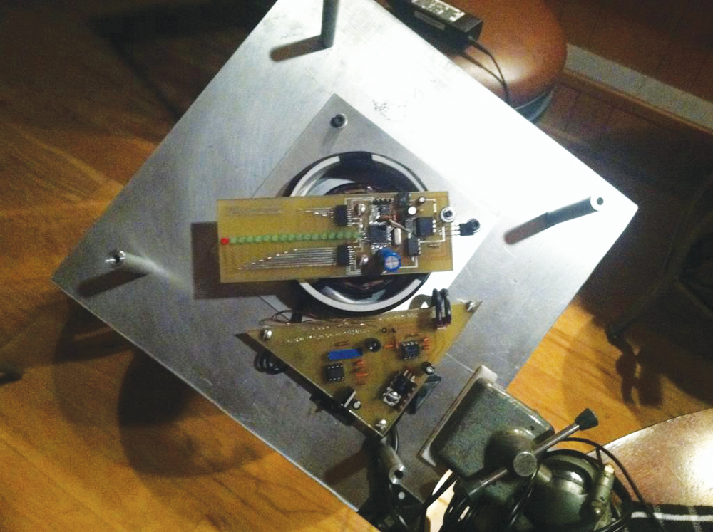
Once the propeller and the mechanical components have been assembled, the clock can be placed in a suitable enclosure. This could be a wooden or metal frame, or it could be a more decorative case made from glass or plastic. The enclosure should be large enough to accommodate the propeller and the mechanical components, and it should be sturdy enough to support the weight of the clock.

Finally, the clock must be tested and calibrated to ensure that it is functioning properly. The propeller should rotate smoothly and consistently, and the markings should be clear and easy to read. Any adjustments or repairs that are needed should be made at this stage to ensure that the clock is accurate and reliable.

Overall, building a propeller clock is a challenging but rewarding project that requires a combination of mechanical skill, attention to detail, and artistic flair. With careful planning and execution, it is possible to create a unique and visually striking timekeeping device that will be a source of pride and enjoyment for years to come.

LED Propeller Clock : 19 Steps (with Pictures)

propeller clock project

Use picture as a guide if needed. Another thing performed in this interrupt is that, the previous time gets divided into number of segments, and the concluding result will be stored in the timer register TH1 After verifying your program you can generate. A motor spins the "propeller", and a small microprocessor keeps track of time and changes the pattern on seven LEDs with exact timing to simulate an array of LEDs. Thank you for your time Jake L. The skin isn't very fond of super hot things. On the spinning board, the transformer secondary will pulse at the FSK frequency of the transformer primary and FSK is decoded with a simple slope detector.

Next

Propeller Clock : 9 Steps

propeller clock project

Testing PC to PC serial communication with a serial terminal PuTTY was able to transmit up to 28800 baud without any observable errors. . The 12V power is transferred from the base to the control board via 2 carbon brushes see image below while the control board is spinning at ~600RPM. Future Scope Once developed at a large scale and used with multicolor LEDs can be used to replace LCD screen. Minimum 500mA and Maximum 1000 mA current supply must provide to Motor to get a proper rotation speed. The microcontroller is interfaced with an interrupt circuit and an output port has been connected to 8 LED's. Introduction Conventional methods of displaying images or massage to public are using LCD display and dot-matrix LED displays.

Next

Propeller clock

propeller clock project

But for the purpose of this project, it is necessary to use 6V-12V range motor and therefore a 6V-9V range motor is used. It can be used in place of various LCD displays when packaged in a proper way thereby leading to a cheaper way. Phototransistor In order to know when the system should restart displaying the current image or massage on the propeller clock, we need a known reference point called home point. Following Figure 5 shows the most reliable way of create mechanical assembly that we used. Microcontroller AT89C2051:- This project is based on the microcontroller AT89C2051, which is a derivative of 8051 family.


Next

Propeller Display : 11 Steps (with Pictures)

propeller clock project

On the basis of the ABOVE diagram , coding is done and then the display is formed. Balancing the PCB plate over the motor took a lot of our time. This display consists of just 8 bright LEDs which are rotated to show the display. I don't have access to Kail and can not open one of your file, so can i request the hex file not formated in intel hex format? Where : São Paulo, Brazil. Subtract the answer from 256, and load the Result in th0. PORTA and some pins of POARTB are connected to LED panel and POARTC is used to connect push buttons. The motor performance is very important in circuit design.

Next

My Story: DIY LED Propeller Clock

propeller clock project

If there is a more frame rate, it cause to the less flickering of the picture. This project is a cylindrical type digital propeller clock with help of some mechanical assembly, LED count and hardware requirement. I've built a few LED signs, but they get boring because I already know the message. So, if someone is observing the images at least 16 frames per second, then they appear to be continuous. The current can be supplied using that, because of the brush keeps its contact with the cylindrical disc. It is very important to bend the legs exactly as shown, or the positive and negative can get mixed up.

Next

Propeller Clock [pd49epvwj0l9]

propeller clock project

The motor spins at a constant rate such that the LEDs rotate around a centre pivot point. Few times, I have to connect the connector to 9 volt battery like 20-30 times just to get the proper output. Now, reset the video RAM pointer and character segment pointers to their initial respective 6. When : 20 12. The diode at the base of the transistor clamps the base of the transistor to ground to prevent negative signal voltages from causing damage to the transistor.

Next

How to Make Propeller Clock Using Arduino Uno

propeller clock project

It is a main part of the circuit. Turbidity is an optical characteristic or property of a liquid, which in general terms describes the clarity, or haziness of the liquid. It is an illusion, but it works nicely. A limited number of leds are placed in a row and attac hed to a rotating board. This phenomena is known as Persistence of Vision POV that gives the illusion of a static stable display. Be very careful when soldering the digital pins; it is very easy to accidentally connect to digital pin connections. The main goal of this step is to keep the DC motor in an elevated position.

Next

Propeller clock using Microcontroller

propeller clock project

I had my eureka moment when I realized that all I really care about is transmitting RS232 in one direction. All the synchronizing can be implemented through software. The mechanical scanning mechanism, which is performed in the clock when the motor is turned on, the connected seven LEDs are scanned line by line at a very fast speed which makes the observer to observe those led display clock. Therefore a remote system can be used to set time and date. Pradeep Mittal Himanshu Chaudhary Chandan Sah Deepika Grover Section-E3106 Abstract:This project is a different view of holographical clock construct in linear array arrangement. For me, the soldering iron method worked best, but feel free to use your own judgement.


Next

Propeller Clock Project Report [3no705v72xld]

propeller clock project

Also the board was built a year before the clock was actually up and running so there were several modifications on the wiring, which resulted in some brittle connections and intermittent operation so I just needed to build a new one. Figure 4: Display a number using column of 7 LED s Speed of LED s Frame Rate The rotational speed of the LEDs is directly affects to the frames per second. I have seen most designs use magnet wire handwound in a circle or in a helical coil structure. The pin diagram of the ATmega32A microcontroller given below in Figure 1, Figure 1: Pin Diagram of ATmega32A Motor All types of motors used to convert electrical energy into mechanical energy. The value in the W register when Delay gets called effects the width of the digits. The circuit is pretty much identical to previous versions except for a few modifications.

Next