Introduction to three phase system. Three 2022-10-10
Introduction to three phase system Rating:
4,3/10
677
reviews
A three phase system is a type of electrical power distribution system that uses three separate conductors to transmit electricity from a power source to end users. It is commonly used in commercial and industrial settings where there is a high demand for electricity.
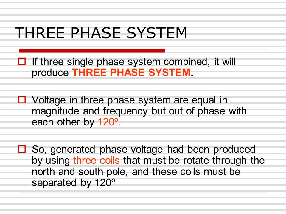
In a three phase system, there are three electrical conductors, each carrying an alternating current (AC) of the same frequency, but with a phase difference of 120 degrees. The combination of these three currents produces a more stable and consistent flow of power compared to a single phase system, which only has one conductor.
One of the main advantages of a three phase system is that it can transmit more power over longer distances with less loss of energy. This is because the three phase system allows for a more balanced distribution of power, reducing the strain on individual conductors and minimizing the resistance that can cause energy loss.
Another benefit of a three phase system is its efficiency. Because the three phase system uses three separate conductors, it is able to take advantage of the natural cancellation of positive and negative forces, which reduces the amount of heat generated and improves the overall efficiency of the system.
In addition to its benefits in transmitting power, a three phase system is also well-suited for certain types of electric motors. Many industrial motors are designed to operate on three phase power, and using a single phase system to power them can result in reduced performance and shortened lifespan.
Overall, a three phase system is an important part of the electrical power distribution system, providing a stable and efficient way to transmit electricity to end users in commercial and industrial settings.
Three
Magnetic force is strongest at the North and South ends of the magnet. Connect the wattmeters as shown in Figure 12. Similarly, the circuit elements that comprise the load are connected to form either a Y or a Δ. Three-phase has this delay provided naturally. Let's have a professional and meaningful conversation instead. What does 3-Phase Even Mean? While they may require an initial cost to start off with, they'll pay themselves off in the long run.
This means that the two-wattmeter method can also indicate the total reactive power in the three-phase loads and also the power factor see Figure 3-24. In the case of Since the line current in the balanced delta-connected loads, if this equation is substituted into equation 3. This means that the total power in any balanced three-phase load Δ- or Y-connected is given by equation 3. However there is a way we can increase the max power capacity economically — 3-phase PDU. In the connection shown in Figure 13 a false neutral has been created by connecting the voltage low terminals of all three wattmeters together. As a definition, the voltage across the load impedance and the current in the impedance can be used to compute the power per phase. The cross section area of the neutral conductor is half of the live wire.
A typical three-phase service for smaller facilities such as a home shop or commercial building is the 208VWye arrangement system. Fewer power failures will increase the life span of your equipment as they're less likely to be affected by subsequent power surges. Using the example above, we would need 50 3-phase PDUs compared to 86 1-phase PDUs to power 215kW worth of hardware. If the three loads impedances Z 1, Z 2 and Z 3 has the same magnitude and phase angle then the three phase load is said to be a balanced load. Three-phase systems are the method by which almost all electrical power is generated and distributed. Regardless, it is critical to understand these systems since they drive nearly every industrial motor, and smaller branch circuits feed every one-phase receptacle and lighting system. Companies affiliated with GlobalSpec can contact me when I express interest in their product or service.
Running this network give us a unique vantage point to track the evolving cost of bandwidth around the world. CHAPTER 12 Three-Phase Circuits IN THIS CHAPTER DESIGN EXAMPLE—Power Factor Correction 12. Why is Three-Phase Ideal for Motors? This blog is a brief Electrical Engineering 101 session going over specifically how power distribution units PDU work, along with some good practices on how we use them. This can be proven in a star-connected load mathematically using the power reading of each meter as If the difference of the readings is computed, which is times the total three-phase reactive power. The sum of the line currents in the 3-phase system is equal to zero, and their phases are differentiated at an angle of 120º The three-phase system has four wire, i.
Basic three phase power measurements explained in details
For a given number of wires, N, N-1 wattmeters are required to measure total quantities such as power. The three phase system induces in the generator which gives the three phase voltage of equal magnitude and frequency. This technical article describes the basic principles of three phase systems and the difference between the different measurement connections that are possible. Every line L will be alternately pushing and pulling current to and from the neutral N , but not all at the same time. Another type of arrangement is the Delta system. That is considered as the main component of any device and project.
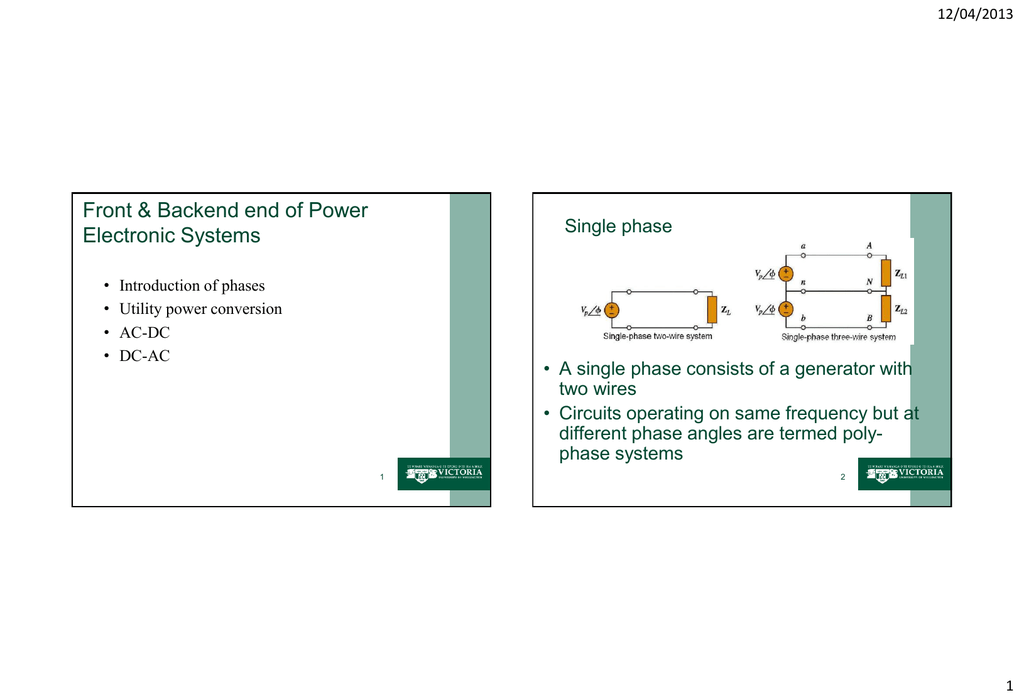
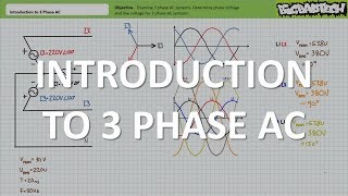
Let's assume that the angle between the phase voltage and the phase current is θ, which is equal to the angle of the impedance. Four-wire Wye systems on the other hand include a neutral wire, so the voltage from each phase to neutral provides a lower voltage single-phase source. One complete sine wave cycle is one phase of 360 degrees, and running at 50Hz means there are 50 cycles per second. Figure 1 — Three-phase voltage waveform This can be represented diagrammatically by both waveforms and a vector diagram Figure 2. What is the correct resistance from neutral to earth ground? Figure 10 — Single-phase, two-wire and DC measurements In this system, shown in Figure 11, the voltages are produced from one center-tapped transformer winding and all voltages are in phase. Poly-phase Systems In a poly-phase system, the AC sources operate at the same frequency but different phases.
A 3-phase PDU of the same US specs above has a capacity of 8. We recall that AC is preferable to DC because voltage levels can be changed by transformers. A power analyzer with vector mathematics capability will also convert phase to neutral or wye quantities to phase to phase or delta quantities. If the load impedances are not equal the load is said to be unbalanced. The line voltage is 400 V. Therefore, the phase active power and the total active power are If the relationship between the phase voltage and the line voltage is used, the total active power becomes identical to the equation developed in equation 3.
That is, it would cost an additional massive amount of money to add infrastructure to deliver two more phase Line wires. If we need more machines and the total sum power goes above 5kW, we'd need to provision another power source. This connection allows the addition of 3rd harmonic elements to results the current movement in the neutral in place of creating large voltage. Figure 2 — Three-phase voltage vectors Why using three phase systems? In a Simplified design Tesla's invention of alternating currents was born out of his discovery of rotating magnetic fields. Thanks for dropping by! Industrial control systems are almost always supplied from a three-phase main voltage service. In a single phase power system, this means the currents moves in one direction before reversing, In other words, there are brief moments where there is no voltage running through the current. .
The delta connection is shown in the figure below. In the connection shown in Figure 13 a false neutral has been created by connecting the voltage low terminals of all three wattmeters together. In this post we will discuss the balanced three-phase system. And finishing the phase, the South end leaves returning the current back to zero. Figure 11 — Single phase three wire wattmeter method Where three wires are present, two wattmeters are required to measure total power.