Dfd diagram for student information system. Draw DFD for Student Information System 2022-10-30

Dfd diagram for student information system Rating: 9,6/10 1992 reviews

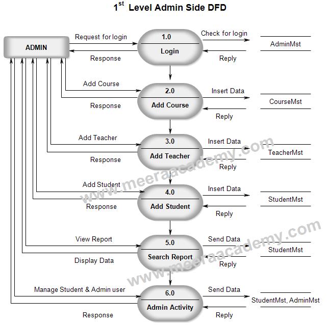
A data flow diagram (DFD) is a visual representation of the flow of data through a system. It is commonly used in the design and documentation of information systems, particularly in the field of software engineering. A DFD for a student information system (SIS) would show how data is input, processed, and output within the system, as well as the various entities (e.g. students, courses, teachers, etc.) that interact with the data.

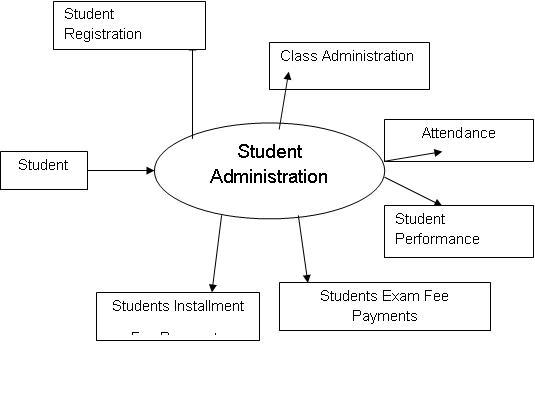
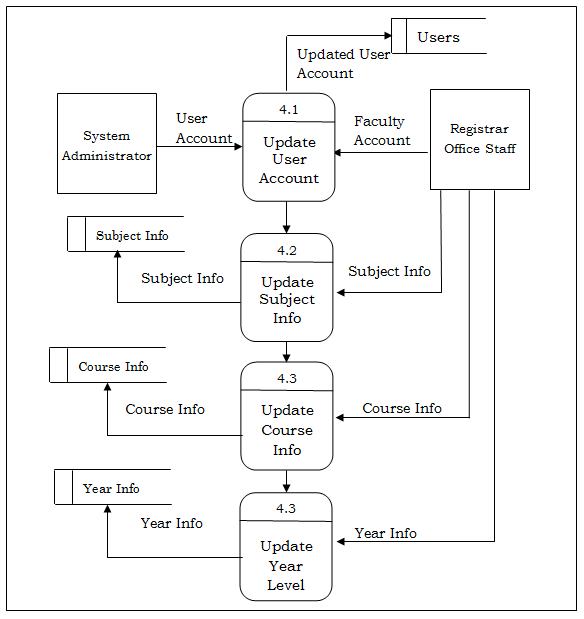
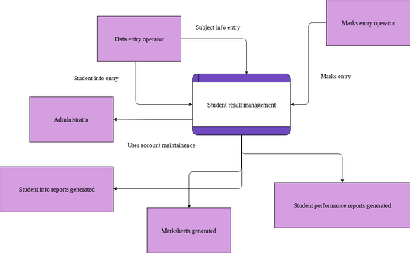
One key element of a DFD for an SIS is the input process. This could include data that is entered manually, such as when a student registers for a course, or data that is imported from external sources, such as transcripts or test scores. The input process would also include any data validation or error checking that is necessary to ensure the integrity of the data.

Once data has been input into the system, it will typically be processed in some way. This could involve calculations, such as when grades are computed based on assignments and exams, or it could involve storing the data in a database for later retrieval. The processing process may also involve data manipulation, such as when a student's schedule is created based on their chosen courses.

The output process is the final step in the data flow through the SIS. This could include generating reports, such as transcripts or class lists, or providing access to the data through a user interface, such as a student portal.

In addition to the input, processing, and output processes, a DFD for an SIS would also include various entities that interact with the system. These could include students, who enter and receive data through the system; courses, which are the primary focus of the system; and teachers, who may input grades and other information related to their courses. Other entities could include administrators, who may have access to higher levels of data within the system, and external agencies, such as accrediting bodies or financial aid offices, which may receive data from the SIS.

Overall, a DFD for an SIS serves as a useful tool for understanding the flow of data within the system and identifying areas where improvements or changes may be necessary. It also helps to document the system's design and functionality, making it easier for others to understand and work with the system.

Student Admission System DFD

dfd diagram for student information system

Authorized users can also change their password. Student Details: In Student Details the whole personal details of any student is stored. It also identifies internal data stores of Student, Semester, Faculty, Subject, Class that must be present in order for the Student system to do its job, and shows the flow of data between the various parts of Timetable, Class, Semester, Student, Faculty of the system. . Data flow diagrams are commonly used during problem analysis. It stores all of the data inputs and secures them until later use. IT and Cloud architecture tools for all platforms.

Next

Data Flow Diagram (DFD) of Registrar Grade Record Management System

dfd diagram for student information system

The student admission system is a project that delivers internet-based enrollment processing that is efficient. It contains all of. . In order to access the system, user is required to enter their user ID and password. The Registrar Grade Record Management System offers several benefits, such as: reliable and complete information; easily accessible and accurate student record reports; high quality information; reduces errors in the result; produces output in greater quantities and of better quality; and provides an electronic tool that is user friendly and easy to use. The users will need to enter their user id and password to be able to access the developed system.

Next

New Level 1 DFD(Student Information System [classic]

dfd diagram for student information system

You will highlight the main functionalities of Student Feedback. DFD Level 1 provides a more detailed breakout of pieces of the 1st level DFD. This means that system should work as how the manual enrollment does. A back-up server will be provided to assist the main server in-case the main server bug downs. Student Enrollment System Data Flow Diagram Pdf You may download the Data Flow Diagram for Student Enrollment System PDF by clicking the button below. The existing system for processing and issuance of grades is paper-based and student grade report cannot be generated instantly. Conclusion The data flow diagram for the student information system depicts the movement of data from one level to another.

Next

A Data Flow webapi.bu.edu

dfd diagram for student information system

Fast, accurate and reliable services will be offered to the community, accessible and relevant information for the Administrators. . Note: The last level DFD level 2 is not required all the time. It contains all of the userflow and their entities such all the flow of Student, Feedback, Class, Feedback Type, Faculty, Subject, Teacher. Remember that when defining the sub-processes of level 1, this level may have several examples.

Next

DFD for Student Management System

dfd diagram for student information system

The Level 0 or Context Diagram illustrates the single and primary process of the student admissions system, as well as the principal users and data. College administration: College administration stores the student information in student information record. Faculties: Faculty information which will be useful for the instructors and separating the sections of the students. Starting from the registration process, a student may come to the college for the admission in a particular faculty and for a particular course and subject matter. The Level 0 or Context Diagram depicts the single and primary process of the student admission system, together with the primary users and data.


Next

Student Feedback System Dataflow Diagram (DFD) FreeProjectz

dfd diagram for student information system

It may require more functionalities of Student to reach the necessary level of detail about the Student functioning. In addition, a labeled arrow is used to indicate the flow of data. For example: Student Information System DFD Level 0 The example illustrates the entire concept of the project in a single step. Dental Clinic Data flow diagram is often used as a preliminary step to create an overview of the Dental without going into great detail, which can later be elaborated. This is the high level among the three and is more detailed. Data Flow Diagram Symbols Notation Data Flow: The data that flows between external entities, processes, and data stores is known as data flow.


Next

Data Flow Diagram For Student Management System

dfd diagram for student information system

Exam Paper Repository System Data flow diagram is often used as a preliminary step to create an overview of the Exam Paper without going into great detail, which can later be elaborated. It may require more functionalities of Student Feedback to reach the necessary level of detail about the Student Feedback functioning. It contains all of the. Here students search easy python projects and get easily download free php. Data Flow Diagram for Student Enrollment System PDF You can also modify its content to complete your project requirements and needs. These entities will be the source of inputs and receive outputs.

Next

Student Information System Dataflow Diagram (DFD) FreeProjectz

dfd diagram for student information system

It too may access the student database for updating the student attendance details and to categorize the students relating to various sections and semesters. Now, are you curious about the symbols that we used in the above illustrations? Product Management tools + Software Architecture tools. The student admission system is a project that provides efficient processing of enrollment through the internet. Storing of paper documents gets very voluminous. It is common practice for a designer to draw a context-level DFD first which shows the interaction between the system and outside entities.


Next