4 bit parallel adder theory. 4 2022-10-30

4 bit parallel adder theory Rating: 8,9/10 551 reviews

A 4-bit parallel adder is a digital circuit that is used to perform arithmetic operations, specifically addition, on two 4-bit binary numbers. It is called a parallel adder because it performs the addition simultaneously on all the bits of the two input numbers.

The basic principle of a 4-bit parallel adder is the same as that of a 1-bit adder, which consists of two inputs (A and B) and a sum output (S). The input A and B can either be 0 or 1, and the sum output S is calculated based on the following truth table:

ABS
000
011
101
110

In a 1-bit adder, the sum output S is equal to the exclusive OR (XOR) of the two inputs A and B. The exclusive OR operation is a logical operation that returns a 1 if one of the inputs is 1 and the other is 0, and returns a 0 if both inputs are the same.

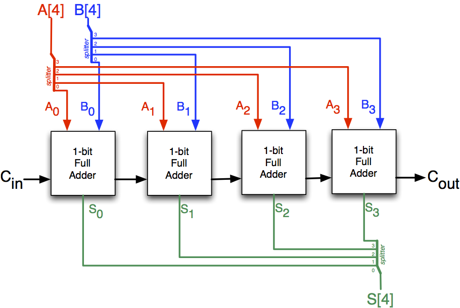
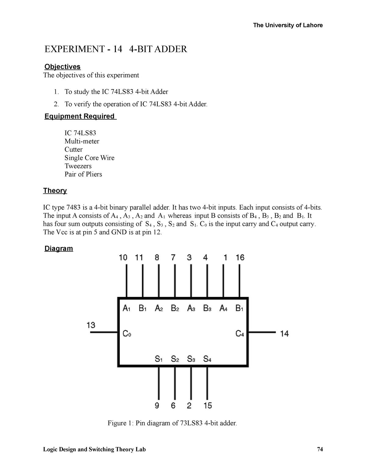
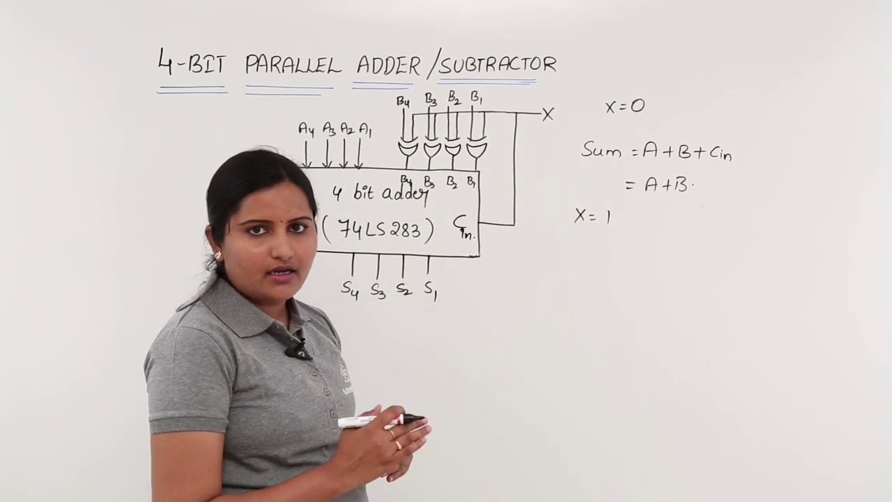
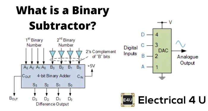
In a 4-bit parallel adder, the two input numbers are represented by four bits each, and the sum output is represented by a 5-bit number. The 4-bit parallel adder consists of four 1-bit adders, one for each bit of the input numbers. The sum output of each 1-bit adder is fed as an input to the next 1-bit adder, along with the carry-in bit (Cin) from the previous 1-bit adder. The carry-in bit represents the carry-over from the previous addition, which occurs when the sum output of a 1-bit adder is equal to 2 (i.e., 10 in binary).

The 4-bit parallel adder also includes a carry-out (Cout) bit, which is the carry-over from the addition of the most significant bit (MSB). The carry-out bit is important because it indicates when the sum of the two input numbers is greater than 15 (i.e., 1111 in binary), which is the maximum value that can be represented by a 4-bit number.

In summary, the 4-bit parallel adder is a digital circuit that is used to perform arithmetic operations, specifically addition, on two 4-bit binary numbers. It consists of four 1-bit adders, a carry-in bit, and a carry-out bit, and it performs the addition simultaneously on all the bits of the two input numbers. The 4-bit parallel adder is an important component in many digital systems and is widely used in computers and other electronic devices.

Four Bit Adder Verilog Code

4 bit parallel adder theory

Output carry generally labelled as C-OUT, whereas normal output labelled as S, that stands for SUM. The first two inputs are A and B and the third input is an input carry as C-IN. Carry output C 2 is then added to the next significant bits A 2 and B 2 producing sum output S 2 and carry output C 3. Adder circuit is classified as Half Adder and Full Adder. S1, S2, S3 are recorded to form the result with S0. You know how to do addition using step-by-step.

Next

4

4 bit parallel adder theory

The role of C pin is to determine the overflow in the unsigned numbers. Two types: Half-subtractor and Full-subtractor. XOR gate has 2 inputs, only one of which being Linked to the B, the other to the input k. Then the third input is the B1, B2, B3 EXORed with K to the second, third and fourth full adder respectively. A few examples of these ICs are as follows. Variables Inputs: a 4 bit , b 4 bit Outputs: sum 4 bit , carry 1 bit Others: carryValuesFromFullAdders 5 bit With this, we store carry values and use this value next step.

Next

4 Bit Parallel Adder Circuit Diagram

4 bit parallel adder theory

This is further added to A to carry out the arithmetic subtraction. What is Parallel Adder In modern Integrated Circuits, the most basic and widely used component are Binary Adders. Hence there is no Carry propagation. The major drawback of this Adder is the Propagation Delay. I tried to tell these in a picture: If we want to write an algorithm for these, how to do this? This can be done by cascading four full adder circuits as shown in Figure 5. It is one of the components of the ALU Arithmetic Logic Unit. So for the two-bit number, two adders are needed while for four bit number, four adders are needed and so on.

Next

5.9: FOUR

4 bit parallel adder theory

In case of addition it would be carry while in case of subtraction it would be borrow. The final output generated is a sum of four bits and a carry out C 4. We just have to feed 4 bit 2 numbers at input and power supply. We know that the range of 4-bit unsigned numbers is 0 to 15 and range of 4-bit signed numbers is -8 to 7. Procedure Finally, as being one of the outputs of the 2nd full adder, C0 gets serially passed. What are the inputs and outputs of a full adder? S1, S2, and S3 are recorded in order to build the outcome with S0. The operation is performed depending on the binary value the control signal holds.

Next

Parallel Adder and Parallel Subtractor

4 bit parallel adder theory

The least significant bits A 1, B 1, and C 1 are added to the produce sum output S 1 and carry output C 2. The operation is A+B which is simple binary addition. But in this system we directly add the whole binary number to another whole binary number at a time with the help of arithmetic circuits. For reading more about Full-adder and Half-adders check: How to design Half adder and Full adder circuits? In simple input to this XOR gate would be B. Fig 7 shows block diagram of Carry Increment Adder where the inputs A and B of 8 bits are added using 4-bit Ripple Carry Adders.

Next

How to Design a Four bit Adder

4 bit parallel adder theory

The output carry is designated as C-OUT and the normal output is designated as S which is SUM. What is a 4-bit group? The simplest multi-bit adder is the Ripple carry adder, shown below. What is a 4-bit number? Which is nothing but our subtraction. This Parallel Adder circuit also reduces propagation delay. An AND gate is a logic gate having two or more inputs and a single output. The least significant bits A 1 , B 1 , and C 1 are added to the produce sum output S 1 and carry output C 2. The parallel subtractor can be designed in several ways including combination of half and full subtractors, all full subtractors or all full adders with subtrahend complement input.

Next

What are the inputs in the 4

4 bit parallel adder theory

In practical situations it is required to add two data each containing more than one bit. Access OR, AND and XOR gates details from here. This can be done by cascading four full adder circuits as shown in Figure 5. There are three inputs and two outputs. Half adders are practically used in digital measuring devices like calculators.


Next

verlog code for 4 bit parallel adder

4 bit parallel adder theory

Parallel Subtractor — A Parallel Subtractor is a digital circuit capable of finding the arithmetic difference of two binary numbers that is greater than one bit in length by operating on corresponding pairs of bits in parallel. The Carry Look Ahead CLA logic circuit block consists of four 2-level implementation logic circuits which generate carry signals C1, C2, C3, and C4. When no carry occurs, higher 4 bit numbers are summed as output. In this tutorial, we will talk about 74LS83 4-bit full adder IC. The input of the Full Adder is the carry bit from the previous Full Adder. Based on information provided at registration country, job function, industry, etc. The simplest form of addition is shown in the table below.

Next

Parallel Adder

4 bit parallel adder theory

A1, A2, A3 are direct inputs to the second, third and fourth full adders. What is the maximum output value in a 4-bit adder circuit? We make our mailing list available for purchase. Block Diagram of full-adder is discussed next:. After adding higher 4 bits and lower 4 bits of A and B respectively, the conditional increment increases the value of higher 4-bit numbers by 1 and the carry occurs in lower bits. It consists of full adders connected in a chain where the output carry from each full adder is connected to the carry input of the next higher order full adder in the chain.

Next

CircuitVerse

4 bit parallel adder theory

Always, the carry value is add to next step and the sum value is written to result. Parallel Cellular Automata Machines CAMs are incorporated with Parallel Adder Circuits for Parallel Computing. After that, we will learn to implement 4-bit full adder functionality using 74LS83. Then the third input is the B1, B2, B3 EXORed with K to the second, third and fourth full adder respectively. As the name implies, a four bit full adder can add four input bits. Half-adders: It is used for addition of Least significant digits. O XOR b1 we would be having B2, 0 XOR B3 we would be having B3.


Next